Pharos Controllers support numerous serial communication ports and optional Remote Devices and the following advanced triggers & actions, together with conditions, variables and Lua scripts, provide powerful show control functionality. Indeed, above and beyond a Controller's lighting & AV control capabilities, a Controller can be used to tie together numerous pieces of equipment with various interfaces to yield a robust and fully integrated show control solution.
The revised LPC and TPC with EXT hardware has 8 inputs that can be configured as digital or analog inputs in the Interfaces tab of the Network view. The RIO 80 and RIO 44 have inputs that can be configured as digital or analog inputs in the Remote Devices tab of the Network view.
Use the Controller and Input settings to specify which Controller’s analog input should be considered the input source. Alternatively, leave the Input set to Any to match any of the inputs of the Controller and to capture the input as a variable. To use a RIO's input as the input source, change the Device from Local and select the RIO number, or leave this as Any.
Now you should specify the range of voltage to trigger on. You can choose whether to trigger every time the voltage changes within the specified range ("Changes in range"), or to only trigger when the voltage enters the specified range ("Enters range"). "Enters range" is generally more useful when you are using analog inputs to trigger timelines, but "Changes in range" would be required if you were using an analog input as a variable passed to a Set Intensity action to control the intensity for a group.
The voltage range of a Controller's or RIO's analog input can be configured in the Network view. The smallest measurable voltage change is 0.25V.
RS232EIA-232; an industry standard communications protocol for computing and telecommunications equipment. remains a very popular protocol for interfacing equipment and the RS232 port of a Controller or Remote Device can be configured to support most common data formats. RS485EIA-485; an industry standard communications protocol for computing and industrial equipment. is a more robust alternative to RS232 (better noise immunity, longer cable lengths and faster data rates) and is a widely supported protocol. A Controller or Remote Device can be configured to receive RS232 full-duplex or RS485 half-duplex in the Network view, see Controller interfaces and Remote Devices. A TPC with EXT can receive RS232 full-duplex.
To receive serial from a Controller's serial port, leave Device as Local and use the Controller setting to specify which Controller's serial port should be considered the input source.
If you're using an RS485 expansion module with the original LPC hardware, select which module should be the input source by setting the number next to the Device:
| 1 | Controller serial port |
| 2 | 1st RS485 expansion module |
| 3 | 2nd RS485 expansion module (only used if two RS485 modules are connected) |
For the LPC X, the number next to the Device setting selects which of the two RS232 ports should be the input source.
Alternatively, set the Device to a RIO and select the RIO number.
Now define the string of input characters to be matched as the trigger. There are three formats in which serial strings can be entered:
| Hex | A series of hexadecimal characters (0-9, a-f, A-F) where pairs of values are interpreted as a byte. |
| Decimal | A series of decimal characters (0-255) separated by "." characters. |
| ASCII | A series of ASCII characters. The special characters '\n' for new line, '\r' for carriage return, and '\t' for tab are supported. |
Additionally, each byte can be replaced with a wildcard to match a range of input characters and these wildcards can even be captured as variables to determine the trigger's action.
Use the Controller setting to specify which Controller should process the Ethernet input. Select the Ethernet Source (see Controller interfaces) and press Edit to define the string of input characters to be matched as the trigger in much the same way as RS232 (see above).
MIDI"Musical Instrument Digital Interface"; an industry standard communications protocol for musical instruments. is another very popular protocol for interfacing equipment and the MIDI input trigger allows you to define, via a convenient MIDI Message Builder, the type (Short message, MIDI Show Control or Extended) and command string that is to be matched as the trigger. Variables can be captured to determine the trigger's action.
Use the Controller setting to specify which LPC's MIDI port should be considered the input source. To use the MIDI port on a RIO A, set the Device to RIO A and specify the RIO A number, or leave this as Any. In this case, the RIO number will be captured as a variable.
Press Edit to open the Message Builder:
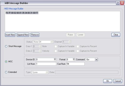
Press Insert New, select one of the three message types and then the specific command and variables.
Press Append New to add and define another command string to be matched, the Raise and Lower buttons can be used to define the matching order.
Press Remove to delete a command string and Clear to delete them all.
The resulting hexadecimal string will be constructed automatically and displayed in the window for reference with question marks ("??") indicating undefined characters in MIDI Show Control (since we do not know in advance how many characters will be captured) or <c>, <d> and <x> as appropriate for Short and Extended messages.
Press Ok to finish.
Use Options > Preferences > Triggers to select the default Short MIDI message data format.
A comprehensive guide to MIDI is beyond the scope of this document, see the MIDI Manufacturers Association for more details, and the manual for the equipment to be interfaced will also certainly be an invaluable reference.
Use the Controller setting to specify which controller should receive the DMX.
Now you should specify which DMX channel to look at and the range of values to trigger on. You can choose whether to trigger every time the value changes within the specified range ("Changes in range"), or to only trigger when the value enters the specified range ("Enters range"). "Enters range" is generally more useful when you are using DMX to trigger timelines, but "Changes in range" would be required if you were using a DMX channel as a variable passed to a Set Intensity action to control the intensity for a group.
The RIO A has a stereo balanced line level audio input that can be used as a trigger.
To use an LPC with an audio expansion module as the input source, use the Controller setting to specify which Controller has the expansion module and leave the Device as Local. If two audio modules are connected, set the port number to match which module should be the input source.
To trigger from a RIO A, set Device to RIO A and select the number of the RIO A, or leave this set to Any to cause the trigger to attempt to match against audio input from any RIO A. In this case, the RIO number will be captured as variable.
Use the Channel setting to specify whether the trigger should match against the left or right audio channel, or the combination of the two (only available for RIO A). Now select which frequency band to use, or leave this set to the overall volume of the channel. Each audio module analyses the incoming audio as 5 frequency bands. Each RIO A can analyse incoming audio as up to 30 frequency bands - see Remote Devices.
The Peak checkbox tells the trigger to match on the decaying level of the last peak in the audio frequency band.
Finally, specify the range of values to trigger on. You can choose whether to trigger every time the value changes within the specified range ("Changes in range"), or to only trigger when the value enters the specified range ("Enters range"). "Enters range" is generally more useful when you are using audio to trigger timelines, but "Changes in range" would be required if you were using an audio band as a variable passed to a Set Intensity action to control the intensity for a group.
RIO D, TPC with EXT
Use this to trigger from a DALI ballast reporting an error. Specify the interface then use All to match if any ballast on that interface reports an error. Alternatively select a single address to match to. Next select the error type to match to.
RIO D, TPC with EXT
To use an LPC with a DALI-S expansion module as the input source, use the Controller setting to specify which Controller has the expansion module and leave the Device as Local. If two DALI-S modules are connected, set the port number to match which module should be the input source.
To use a TPC with EXT as the input source, use the Controller setting to specify which Controller has the EXT and leave the Device as Local.
To trigger from a RIO D, set Device to RIO D and select the number of the RIO D, or leave this set to Any to cause the trigger to attempt to match against DALI input from any RIO D. In this case, the RIO D number will be captured as variable.
The RIO D, TPC with EXT
The RIO D and EXT both recognise DALI input from Light Sensors and Occupancy Sensors that utilise eDALI. When triggering from an Occupancy Sensor select which state is to be matched. When using a Light Sensor, specify what range of light level (0>254) is to be matched. See the table below for light levels:
| Light Sensor Level | Lux Range |
| 0 - 31 | 0.00 - 7.75 |
| 32 - 63 | 8.00 - 15.75 |
| 64 - 95 | 16.00 - 31.75 |
| 96 - 127 | 32.00 - 63.75 |
| 128 - 159 | 64.00 - 127.75 |
| 160 - 191 | 128.00 - 255.75 |
| 192 - 223 | 256.00 - 511.75 |
| 224 - 254 | 512.00 - 1008.00 |
RIO D or TPC with EXT required.
Use this trigger if you want to act upon a change of the electrical state of a specific DALI bus. Buses can be in one of three states: Correct Power, Incorrect Power and No Power.
The BPS has eight buttons which can be used as triggers. The BPI has sixteen buttons which can be used as triggers.
Use the configuration pane to select which Controller should process the trigger. Select the BPS or BPI, button number (or leave as Any - see variables) and the type of button event (Press, Held, Repeat, Release). Setting the button number to Any will capture the pressed button as a variable.
Use this trigger, not the Startup trigger (which will fire before the Remote Devices can be detected), if you wish to act upon the detection of a Remote Device, for example to configure it with settings other than its defaults.
Use the configuration pane to select which Controller should process the trigger and select the Remote Device's type and identification number (or leave as Any - see variables).
Use this trigger if you wish to act upon the loss of a Remote Device, for example to enter a failsafe state and issue a warning.
Use the configuration pane to select which Controller should process the trigger and select the Remote Device's type and number (or leave as Any - see variables).
The set timeline rate action allows the playback speed of a particular timeline to be modified on the fly. You can select which timeline you want to control or get the timeline number from a variable. The rate is specified as a percentage, where 100% is the programmed rate, 200% would be double speed, and 50% would be half speed. The rate can also be driven by a variable.
The set timeline position action allows the playback position of a particular timeline to be modified on the fly, typically the timeline would be paused to prevent it running on by itself. You can select which timeline you want to control or get the timeline number from a variable. The position is specified as a percentage, where 0% is the start and 100% the end. The position can also be driven by a variable.
Use this to set the timecode position for one of the six Time Sources (set the appropriate timecode format).
Use this to inhibit a fixture's RGB levels selectively either to a fixed value or to track a variable. The latter makes for some very interesting realtime effects when used in conjunction with 2D and Media presets. Set a fade time to introduce the change.
Use this to clear one or all fixture RGB inhibitions (see above), set a fade time to release the change(s).
Use this to set an intensity level on DALI fixtures patched to a specified Interface. You can specify whether you want all of the fixtures on that Interface, fixtures in a certain group or a single fixture to be affected by the level change. You can also specify a fade time or choose to reuse the last fade time stored on the ballasts.
Use this to a DALI scene on DALI fixtures patched to a specified Interface. You can specify whether you want all of the fixtures on that Interface, fixtures in a certain group or a single fixture to be affected by the scene change. You can also specify a fade time or choose to reuse the last fade time stored on the ballasts.
Use this to send a DALI command to DALI fixtures patched to a specified Interface. You can specify whether you want all of the fixtures on that Interface, fixtures in a certain group or a single fixture to be affected by the command. DALI commands include off, fade up/down, step up/down, step to min/max, step down and off and step up and on. Where fading is involved, you can specify a fade rate or choose to reuse the last fade rate stored on the ballasts.
Use this to mark all or a single emergency ballast as fixed on the specified interface.
Use this to start a Duration or Function test on all or a single DALI address(es) on the specified interface.
Use this to stop a Duration or Function test on all or a single DALI address(es) on the specified interface.
The Set Text Slot trigger action allows you to change the value of a text slot from a trigger, see the Dynamic Text preset.
You select the slot either by picking from the Text Slot list or by specifying a variable. If you use a variable, the variable must have captured a string in the trigger, and that string must be the name of an existing text slot.
The value to put in the text slot is then selected with the second variable.
Use this to fire a Trigger. You can specify which trigger you want to fire or which variable you want to use to get the trigger number from. You can also choose whether you want test the conditions of that trigger or not.
Use this to run a Lua script, press Launch Editor to open the script editing dialog. If you can not achieve what you want with the triggers and actions provided it is almost certain that a script can be defined to solve your problem.
Pharos Controllers support a scripting language that can be used for handling complicated conditional triggering or other advanced control requirements. The user can write scripts and set them to run in response to any trigger event. From within a script you can do all the things that you can do with a trigger in the triggers screen – access passed-in variables, test conditions and perform actions - but you can also define more complicated conditional statements and perform mathematical operations.
Designer provides sample scripts which are located in Program Files at \Pharos\Designer\resources\scripts\actions.
WARNING: Scripts are an advanced feature intended to solve problems that cannot be addressed in any other way. They are not as user-friendly as the normal triggers interface and incorrectly written scripts will not work as intended and could cause other problems with the operation of your Controller. For help with writing scripts, please see the Trigger Script Programming Guide, or please contact support to discuss requirements for a particular project.
The RIO 08 has eight relay outputs, the RIO 44 has four and the RIO 80 none.
Use the configuration pane to select the RIO, output and the state of the relay.
RS232EIA-232; an industry standard communications protocol for computing and telecommunications equipment. remains a very popular protocol for interfacing equipment and the RS232 port of a Controller or Remote Device can be configured to support most common data formats. RS485EIA-485; an industry standard communications protocol for computing and industrial equipment. is a more robust alternative to RS232 (better noise immunity, longer cable lengths and faster data rates) and is a widely supported protocol. A Controller or Remote Device can be configured to send RS232 full-duplex or RS485 half-duplex in the Network view, see Controller interfaces and Remote Devices. A TPC with EXT can send RS232 full-duplex.
To send serial from a Controller's serial port, use the Controller setting to specify the Controller number, leave the Device as Local and choose a port number. For the revised LPC hardware and TPC with EXT this should be set to 1.
Alternatively, set the Device to a RIO and select the RIO number.
Now define the string of output characters. There are three formats in which serial strings can be entered:
| Hex | A series of hexadecimal characters (0-9, a-f, A-F) where pairs of values are interpreted as a byte. |
| Decimal | A series of decimal characters (0-255) separated by "." characters. |
| ASCII | A series of ASCII characters. The special characters '\n' for new line, '\r' for carriage return, and '\t' for tab are supported. |
Use the Controller setting to specify which Controller should generate the Ethernet output. Define the recipient's IP address and Port, select the messaging protocol (UDP, TCP) and define the string of output characters to be transmitted. The recipients IP address and port number can be passed with variables.
When sending UDP messages it is possible to specify a bus to send from. This will force the UDP packet to be sent from the port number specified in that bus.
When sending TCP messages it is possible to specify a bus to send from. If the selected bus is of type TCP Client, the connection to the third-party device will be created before the message is sent. If the bus is of type TCP, the message will be sent using an existing connection to the third-party device, if one is available, otherwise the data will be sent from a different port to that which is specified in the bus settings.
MIDI"Musical Instrument Digital Interface"; an industry standard communications protocol for musical instruments. is another very popular protocol for interfacing equipment and the MIDI input trigger allows you to define, via a convenient MIDI Message Builder, the type (Short message, MIDI Show Control or Extended) and command string that is to be output.
Use the Controller setting to specify which LPC's MIDI port should be used as the output. To use the MIDI port on a RIO A, set the Device to RIO A and specify the RIO A number.
Press Edit to open the Message Builder:
Press Insert New, select one of the three message types and then the specific command and variables.
Press Append New to add and define another command string to be output, the Raise and Lower buttons can be used to define the output order.
Press Remove to delete a command string and Clear to delete them all.
The resulting hexadecimal string will be constructed automatically and displayed in the window for reference with question marks ("??") indicating undefined characters.
Press Ok to finish.
Use Options > Preferences > Triggers to select the default Short MIDI message data format.
A comprehensive guide to MIDI is beyond the scope of this document, see the MIDI Manufacturers Association for more details, and the manual for the equipment to be interfaced will also certainly be an invaluable reference.
The BPS has eight buttons each with an integral white LED. The BPI has sixteen buttons with a linked output designed to drive LEDs.
Use the configuration pane to select the BPS or BPI, button number (which can be driven by a variable) and the desired LED behaviour. Enabling "Set all other LEDs to default" will set these LEDs to their default values as specified in BPS properties.
Use this to stop a RIO A
Use this to enable or disable eDMX Pass-Thru on an LPC's DMX ports. Choose which port you want to enable or disable by choosing from the port selection box. See patch for more information.
Use this to force the Controller(s) to perform a hard reset which is equivalent to a power cycle. Note that unlike PC based solutions there is no particular advantage or maintenance requirement to periodically reset a Controller, this action is offered purely as a method of resetting the system to a defined, start-up state.